
End Covers
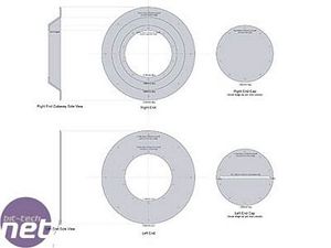
With each end of the case being destined for a different purpose, it meant some variation in the plans. One end was to be an air intake for the radiator and the other to accommodate the slot for the DVD drive. The key things I wanted to accomplish were: to ensure the ends still followed a similar look to each other and the rest of the case, and to conceal the air intake in a practical and industrial looking way, allowing maximum airflow. The covers also had to be easily removable for access to the components that will be located inside each end section.

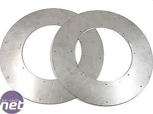
I started with several pieces being laser-cut out of 3mm stainless steel (that's them being cut in the pic above). Laser cutting was essential for accuracy in aligning holes and for perfect circles. If you've ever tried cutting or working 3mm stainless with hand or even power tools, you'll know that you get nowhere fast (well, you do get some lovely worn out or damaged tools). Conversely, with the laser, the total cutting time for these pieces was about 45 seconds!

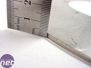
Besides the two big, outer rings that are common to both ends, I also had a few more pieces cut, and some others that you'll see later. The 3mm stainless won't be bending in a hurry (or at all, ever)! The edges were quite sharp so the first task was to run a file around and also sand the sharp edges.
The DVD End Cover
The cover for the DVD Drive-end was the simplest, consisting of two rings of decreasing size and a disc with a slot in it. The plan called for the two outer rings on each end to be secured with my fancy Armor Ring-type fasteners, and the disc in the middle (for a bit of variety) to use short M6 button-head socket screws.
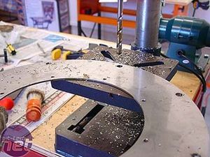
I started by drilling the outermost ring - 4mm inside holes and 8.0mm outer holes. The outer holes are the ones that will line up with the flanges of the end sections of the cylinder.

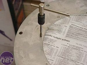
After drilling the inner holes to 4mm, they were all tapped to M5.

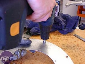
The smaller, inner ring was drilled to 5.5mm outside holes and 5.5mm inside holes. The outer holes serve as clearance holes for M5 screws, while inner holes were tapped to M6. Once everything was drilled and tapped, I used a countersink bit in my cordless drill and gave each hole a quick squirt to de-burr the edges.

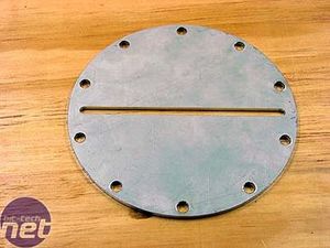
The disc in the middle was drilled out to 6.5mm to provide clearance holes for the M6 screws. I now had to put it all together...

MSI MPG Velox 100R Chassis Review
October 14 2021 | 15:04




Want to comment? Please log in.