Fanbus Chassis
Right, with the board built and the knob lighting figured out it was time to find some way of mounting the whole thing. I decided to use a surplus plastic 5 1/4" drive bay carrier that once held a USB panel.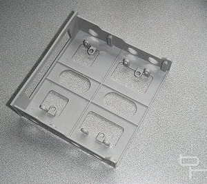
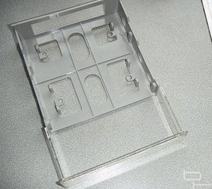
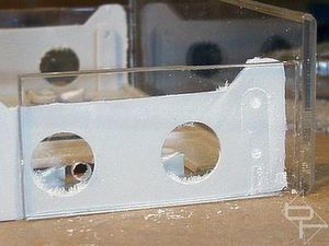
The plastic chassis was slightly too wide and so needed some work to make it fit the front panel.
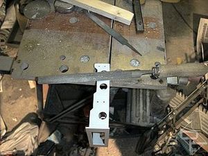
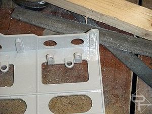
An assortment of files, blood and sweat were used to make the modifications. Those vertical lugs (right) needed to be removed too to accommodate the PCB although the horizontal ones were left as supports for the board. The rotary tool soon made short work of them.
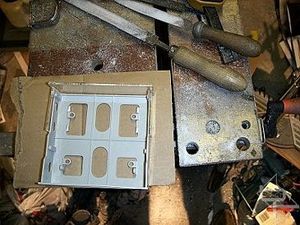
Now that the front panel fitted the chassis, it was fixed in place by drilling two 3mm holes through each side for securing nuts and bolts. The holes were countersunk and countersunk screws used. Otherwise the screw heads would foul on the case when fitting the finished unit. Top down view showing the chassis and front panel fitted (right).
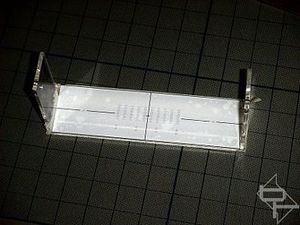
Time to turn our attention to the front panel. After removing it from the chassis I stuck a drilling template to the inner face. The template was designed in a CAD package and printed onto transparent sticky label sheet, similar to my previous decal mod.
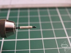
I wanted to drill a matrix of 1mm holes to accept fibre optic cables from the LED's These holes were not to go right through the panel so I resorted to making a hi-tech depth gauge by wrapping masking tape around the drill to mark the desired drilling depth. A few weeks after this I bought a drill press which would have made things much easier!
1mm pilot holes were also drilled for the row of push button switches and the two control knobs. Small pilot holes were used because I was now going to paint the inside of the front panel and I did not want the paint to run through to the front face spoiling it...

MSI MPG Velox 100R Chassis Review
October 14 2021 | 15:04


Want to comment? Please log in.