
HDD Gated Display
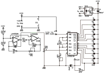
This is identical to the "Classic" version above except the LEDs only light during hard disk activity. Essentially it is an elaborate replacement for the standard HDD LED. Again, there are four variations similar to the "classic" previously shown. The circuit uses an opto-isolator to block or "gate" the current to the LEDs, preventing them from lighting. The input to the opto-isolator is connected to the motherboards HDD LED header. During HDD activity the opto-isolator switches on allowing the LEDs to light. The capacitor C3 helps to "smooth" the effect. You can experiment using different values such as 470uF or 1000uf for a subtle change in effect.
Construction wise, these circuit boards are identical to the standard "classic" versions with just the addition of IC3,C3 and HDD connection fitted. C3 actually replaces the small link on the classic boards. The differences are shown in red on the layout diagrams.
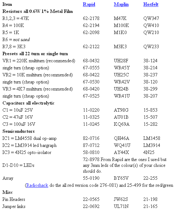
Parts List with order codes for UK and US suppliers
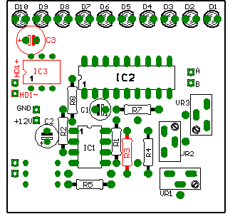
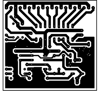
Component layout - top view (left) and Track layout - Viewed from above (right)

The finished board.
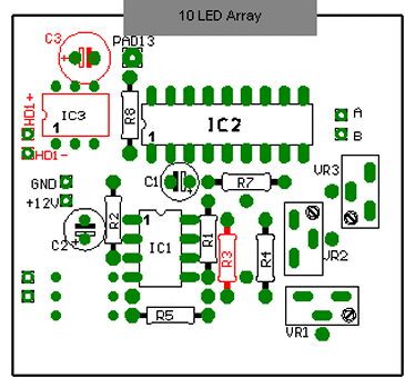
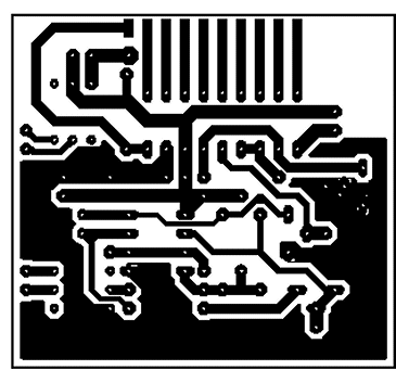
Component layout - top view (left) and Track layout - Viewed from above (right)

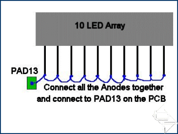
The finished board and a detail of how the anodes are linked together and connected to the board using pad13, indicated by the red arrow.
This is identical to the "Classic" version above except the LEDs only light during hard disk activity. Essentially it is an elaborate replacement for the standard HDD LED. Again, there are four variations similar to the "classic" previously shown. The circuit uses an opto-isolator to block or "gate" the current to the LEDs, preventing them from lighting. The input to the opto-isolator is connected to the motherboards HDD LED header. During HDD activity the opto-isolator switches on allowing the LEDs to light. The capacitor C3 helps to "smooth" the effect. You can experiment using different values such as 470uF or 1000uf for a subtle change in effect.
Construction wise, these circuit boards are identical to the standard "classic" versions with just the addition of IC3,C3 and HDD connection fitted. C3 actually replaces the small link on the classic boards. The differences are shown in red on the layout diagrams.

Parts List with order codes for UK and US suppliers

10 individual LED version
Construction is as before but with no link, (replaced with C3), and the added components IC3,C3 and the connection pins for the HDD. This board has no links. Note the position of R3 which uses the same holes as the classic version previously.

Component layout - top view (left) and Track layout - Viewed from above (right)

The finished board.
Single LED array version
This board has no links. Note the R3 position.

Component layout - top view (left) and Track layout - Viewed from above (right)


The finished board and a detail of how the anodes are linked together and connected to the board using pad13, indicated by the red arrow.

MSI MPG Velox 100R Chassis Review
October 14 2021 | 15:04



Want to comment? Please log in.