One of the points that definitely crosses the mind of folks wishing to jump into the territory of making a case from scratch, is definitely "How do I make everything line up?"
It's an important point to consider, since not having mounting holes line up or components fit into spaces is a real pain. There's a lot to think about when designing a case from scratch, or even just modding an existing chassis in perhaps a more extreme way, because it's easy to miss details or make mistakes. One classic modding method is to use a donor chassis for this. You take an existing case and simply cut out the motherboard tray and I/O area. The handy thing about this method is you know things will fit and the donor case can be any cheap offering you have to hand.

But what if you want to go a step further? Sometimes, trying to add a donor tray just becomes a pain and other times won't work at all. This guide should hopefully help out there. Whilst making a set of mounting points for a motherboard is easy, the real lesson here is how to work with the official specifications - it's a way of thinking.
Working to the Specifications
As you likely know, PC components conform to a number of official spec lists, most commonly ATX, mATX and mini-ITX, plus a handful of others for less common form factors and specific components like power supplies, etc.
You can find PDF versions of the official Spec sheets over at FormFactors.org


But why bother working to these convoluted documents when you can just measure from hardware? Well, for me at least, it's that you get options. Not only can you know the exact dimensions and mounting-hole placements, you can find out things like the gaps between PCIe slots, the size and position of I/O shield cutouts, sizes and layouts of power supplies - you name it. This is immensely powerful when designing a mod, it allows you to push forward and plan ahead with confidence. That, in turn, allows the prospect of more advanced or exciting ideas in the future.

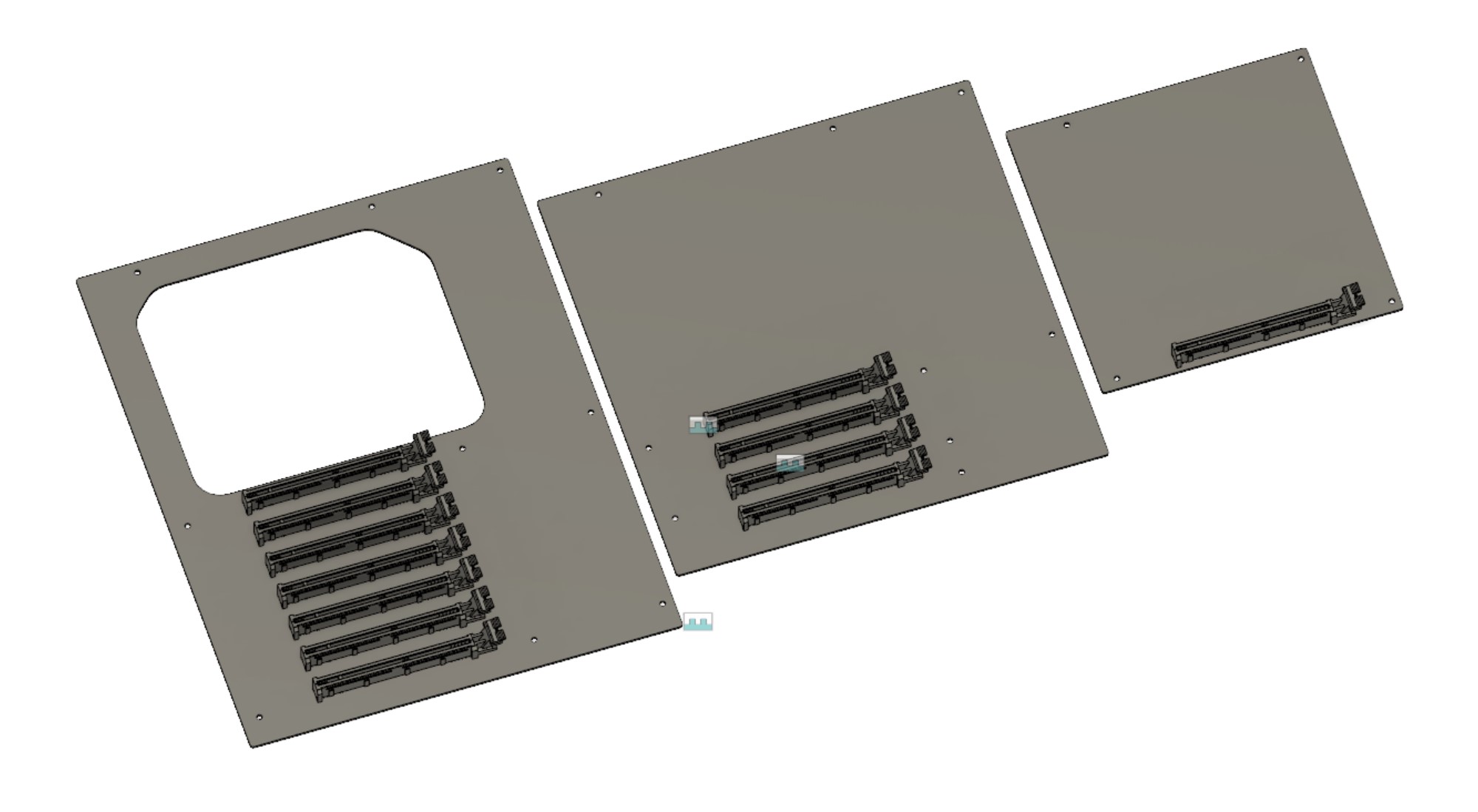
For this guide I'm sticking to just the motherboard mounting holes. I've prepared a bunch of 3D and 2D files based on the various specifications that you can download HERE. Inside you'll have a Fusion 360 3D file containing ATX, mATX and mini-ITX motherboards, along with 2D DXF and PDF files for printing/inserting into other programs.
Whilst I decided not to include things like the PCIe card height or the motherboard I/O cutouts, I have added the PCIe slot locations to the files, which should make it easier to add things later yourself. If you want additional information, it's all in the specifications, and having an accurate version of the board layout should make it much simpler.
Link to Downloadable Files

MSI MPG Velox 100R Chassis Review
October 14 2021 | 15:04


Want to comment? Please log in.